High Voltage and X-Ray Experiments
Text and Graphics Copyright © 2005 − 2008 Henning Umland
The following descriptions are given for the purpose of information only. I do not encourage ANYBODY to conduct experiments like those displayed on this web site, and I do not assume liability for any damage resulting from such experiments. People working with high voltage and X-rays should have a solid background in physics and electronics and should know what they are doing. The high voltage sources described here are much more powerful than generators of static electricity like, e. g., influence machines or Van de Graaff generators. High voltage can kill instantly, X-rays in the long run (radiation sickness, cancer) if not handled properly.
High Voltage Components
First of all, the HV experimenter who wants to work in the range of tens or hundreds of kilovolts is confronted with
the problem that suitable parts are not readily available in electronic stores. In general, they are manufactured by
specialized companies, and they are very expensive, sometimes unaffordable, when purchased new. With some luck, used
parts or NOS (new old stock) parts can be acquired through junk yards, recycling facilities, surplus stores, or Ebay. Prices vary over a wide range. The following is a display of some of the various HV components I was able to procure in recent years. My experimental HV power supplies described later are based on some of these components
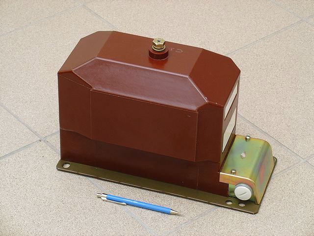
The first photo shows a 100:1 potential transformer (PT). Such transformers are used to monitor 11 kV AC power lines by measuring the much lower secondary voltage with a conventional voltmeter. The transformer is extremely robust and can handle considerable voltage and current overload temporarily. When using the transformer in reversed mode, it is a very nice source for high voltage (AC). Driving the secondary (now primary) coil with 150 V RMS @ 50 Hz yields a peak voltage (PV) of approx. 21 kV at the high voltage terminal (the big screw on top of the transformer). This is about the maximum voltage the transformer can handle at 50 Hz. At this point, core saturation becomes a problem. The wave form of the output voltage gets distorted, the humming noise of the core (magnetostriction) changes due to the increasing amplitude of harmonics, and, more important, the primary current increases rapidly. Since we have a line voltage of 230 V @ 50 Hz in Europe, a step-down transformer is required. Feeding the PT with 115 V AC (resulting in 16 kV PV) for several hours does not cause overheating. Potential transformers are very expensive and hard to get. I was lucky to find three of the same type at a local junk yard (dirt-cheap). They were brand-new, and each one of them was still in a sealed box! This gives me the chance to build a three-phase HV power supply some day. PTs are much more powerful than neon sign transformers or oil burner ignition transformers often used by HV experimenters.
|
100:1 Potential Transformer (Manufacturer: ABB)
This is a 200:1 potential transformer, the biggest and heaviest (31 kg) piece of my small collection (I have two of them now). It is designed to monitor 20 kV power lines. The HV coil can be driven to more than 30 kV RMS (>40 kV peak voltage) without problems.
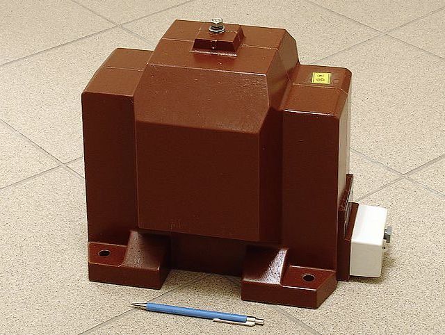 |
200:1 Potential Transformer (Manufacturer: VEB Transformatoren- und Röntgenwerk Walter Matern, former GDR)
Here is another 100:1 potential transformer. In contrast to the above transformers, this one has a floating high-voltage coil. Therefore, it can be used in combination with a full-wave rectifier bridge.
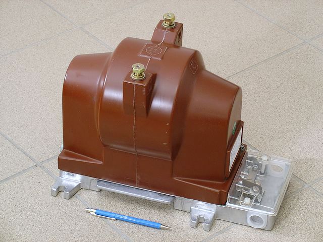 |
100:1 Potential Transformer (Manufacturer: Ritz, Germany)
After some research, I found a supplier of new, commercial grade HV capacitors. I use two types, 50 nF / 20 kV DC and 22 nF / 40 kV DC (see below). These are well suited to the peak voltage of my smaller transformers (approx. 20 kV) since in a Cockroft-Walton circuit, the first capacitor is charged to the peak voltage of the transformer and all following capacitors to twice the peak voltage.
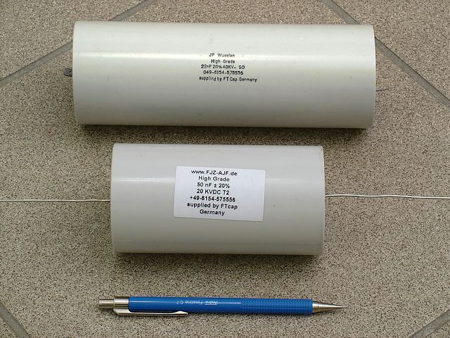 |
High Voltage Capacitors
This is a heavy-duty 0.1 µF / 20 kV capacitor I purchased from a surplus trader. It was manufactured in the former USSR, probably for military equipment.
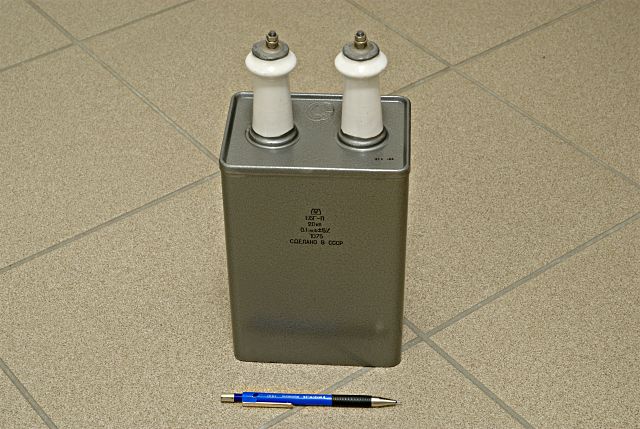 |
0.1 μF / 20 kV Capacitor (СДЕЛАНО В СССР)
This 4 kg monster is an oil-filled 20 nF capacitor rated 67 kV DC (87 kV peak voltage, 100 kV test voltage).
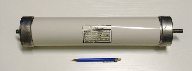 |
20 nF / 67 kV Capacitor (Manufacturer: Hydra, Germany)
This oil-filled 5 μF capacitor is rated 12 kV DC (20 kV peak). It weighs 14 kg. The manufacturer is Roederstein, Germany.
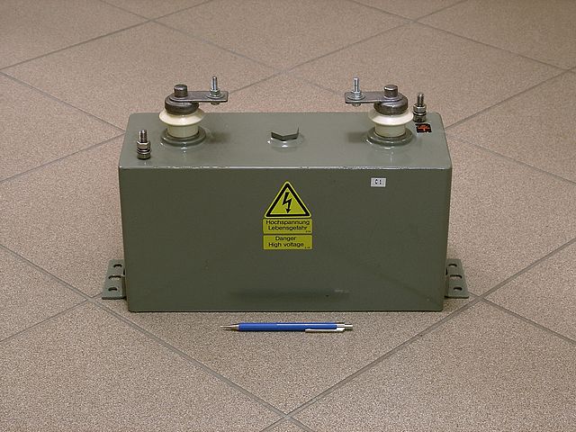 |
5 μF / 12 kV Capacitor (Manufacturer: Roederstein, Germany)
Here are two 6 kV capacitors with a capacitance of 30 μF and 42 μF, respectively. Such capacitors are used in HV power supplies for big linear amplifiers.
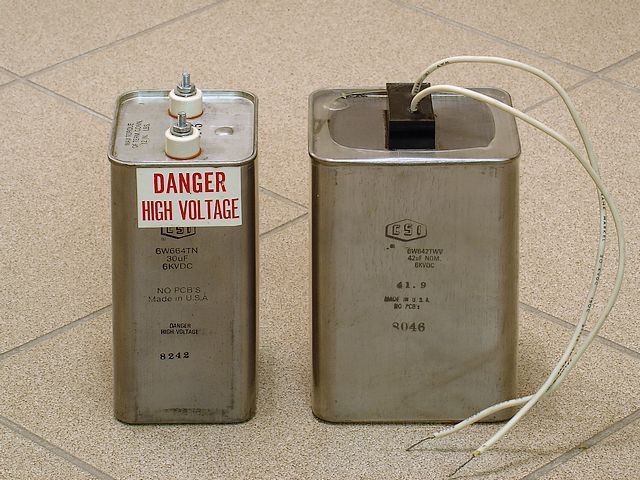 |
6 kV Capacitors (Manufacturer: CSI, USA)
This hunk is a paper/oil capacitor rated 757 μF / 1600 V DC. It can store a maximum energy of 900 Joules. I had the chance to save three of these from the shredder at a local junk yard. Since these capacitors have very low leak currents, I use them in an integrator circuit.
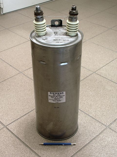 |
757 μF / 1600 V Capacitor (Manufacturer: Siemens, Germany)
For the purpose of current limiting, I use 200kΩ / 500W wire resistors. Although not designed for extremely high voltages, these resistors tolerate short 100 kV pulses without arcing. The power dissipated during those pulses is 50 kW (!).
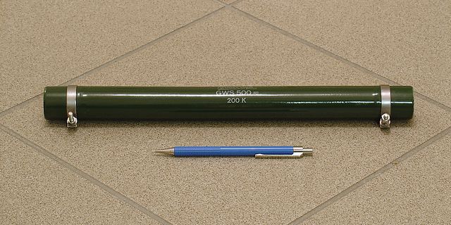 |
200 kΩ / 500 W Wire Resistor (Manufacturer: Rosenthal, Germany)
For my applications, the peak inverse voltage (PIV) of HV rectifiers from microwave ovens (usually 9...15 kV) is far too low. With much luck, I was able to procure a couple of surplus HV rectifiers manufactured by Tesla, Slovakia. The KYY 29/155 was manufactured for X-ray power supplies and is rated 155 kV peak inverse voltage and 100 mA average DC current (350 mA repetitive peak current). Such a rectifier rod is a sealed ceramic tube containing a stack of hundreds of silicon diodes (the forward voltage is about 250 V). These rectifiers have become quite rare. Some surplus traders in Russia still seem to have them in stock. Recently, affordable HV rectifiers from China have become available. The 2CLG80KV/0.2A, which I use now, is rated 80 kV PIV (150 V forward voltage) and 0.2 A average DC current. This diode stack is potted in a black plastic case (see photo).
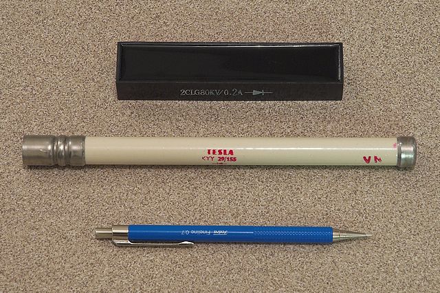 |
Silicon High Voltage Rectifiers
This beauty is an electrostatic voltmeter (1 kV). A static voltmeter has an extremely high internal resistance which makes it the ideal tool for electrostatic experiments. To check the instrument, I charged it up to 1 kV and then disconnected it from the power supply. After eight hours, it still displayed a voltage of 500 V. I repeated the experiment a few days later, during hotter and dryer weather. This time, I had to wait about 45 (!) hours until the voltage dropped to 500 V.
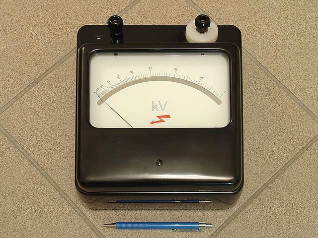 |
Electrostatic Voltmeter
Will be continued...