High Voltage and X-Ray Experiments
Text and Graphics Copyright © 2005 − 2008 Henning Umland
The following descriptions are given for the purpose of information only. I do not encourage ANYBODY to conduct experiments like those shown below, and I do not assume liability for any damage resulting from such experiments. People working with high voltage and X-rays should have a solid background in physics and electronics and should know what they are doing. The high voltage sources described here are much more powerful than generators of static electricity like, e. g., influence machines or Van de Graaff generators. High voltage can kill instantly, X-rays in the long run (radiation sickness, cancer) if not handled properly.
First Experiments
This is a summary of a few initial experiments I made after I acquired the necessary HV components (in no particular
order). I had made HV experiments before, but those were mostly related to static electricity (Van de Graaff generators, etc.) and other smaller equipment (oil burner ignition transformers, microwave oven transformers and rectifiers).
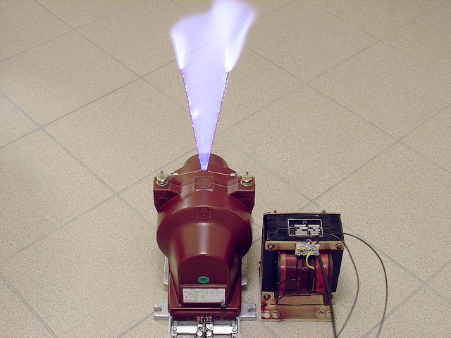
The following picture shows a time exposure of an arc discharge. Attached to the transformer is a so-called Jacob's
Ladder, an arrangement of two horn-shaped wire electrodes. The distance between the electrodes is about 1.5 cm (0.6") at the bottom and 10 cm (4") at the top. Arcing starts at the bottom. Since the density of the plasma in the discharge path is much lower than that of the surrounding air (high temperature!), the arc creates an upward draft and starts climbing between the electrodes immediately after ignition. As the arc rises, it becomes stretched to a point where the discharge suddenly stops. The maximum length of the arc in the photo is approximately 30 cm (1 ft). Jacob's Ladders are used as transient voltage suppressors. The gap between the electrodes has to be adjusted so as to avoid arcing during normal service. When a transient voltage occurs, it triggers a self-extinguishing arc discharge acting as a temporary load and protecting other parts from excessive voltage. Usually, a Jacob's Ladder is used in series with a current limiting resistor to prevent the transformer from overloading. This is because the plasma of the arc has a very low resistance and would almost act like a short-circuit.
|
Arc Discharge at 13 kV RMS (Time Exposure)
The next photo shows a "quick and dirty" set-up of a 2½-stage Cockroft-Walton multiplier (quintupler) designed for a maximum output of 100 kV DC. This is about the maximum voltage that can be handled with such a simple arrangement, because corona discharges are a serious problem. I actually drove it to 105 kV once in order to test the components, but usually I do not go beyond 90 kV. To avoid discharges to ground, the device was put on a sheet of polystyrene resting on plastic cups. The circuit makes buzzing and crackling noises and produces a strong ozone smell. The surrounding air gets so charged up with ions, that I observe a burning sensation on my nose resulting from many small sparks jumping over from the metal rim of my glasses to my skin. Wearing sports shoes with rubber soles, I become charged up myself by the myriads of ions flying around and get a harmless but nasty shock everytime I touch some metal object in the room. On the left side of the picture is an array of heavy duty wire resistors. In addition, each capacitor is in series with a resistor. In case of a spark discharge, the resistors limit the pulse current to about 800 mA. Otherwise, a peak current of several kA would occur, blowing the precious rectifiers apart.
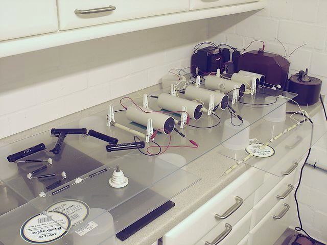 |
Makeshift Multiplier
Here is the circuit diagram:
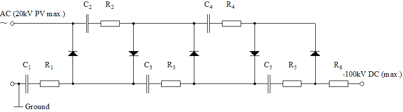 |
100 kV Multiplier Circuit, C1 = 100 nF / 20 kV, C2...C5 = 22 nF / 40 kV, R1...R5 = 5.6 k, R6 = 120 k (10 X 12 k / 10W)
This is not a very good design. With an odd multiplication factor (and number of diodes), the full DC load current flows through the secondary coil of the transformer. This may cause core saturation at higher loads. To avoid this, a Cockroft-Walton multiplier should always have an even multiplication factor (doubler, quadrupler, hexupler, octupler, etc.). With such a design, the transformer is coupled to the circuit through a capacitor which keeps any DC current away from the transformer coil (see my later multipliers).
Here is a single 9 cm (3.5") spark at 90 kV. Due to the current limitation, it is more diffuse and less noisy than a direct discharge from a capacitor. Keeping a respectful distance from the equipment is highly recommended. For safety reasons, the capacitors should be discharged after each experiment.
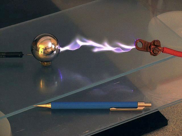 |
90 kV Spark Discharge
Of course, producing X-rays is a challenge to every HV experimenter. Since I do not own a "real" X-ray tube at present, I am looking for alternatives. It would be interesting to know how other vacuum tubes behave when exposed to extremely high voltage. My choice falls on a 4-1000A (EIMAC) which has been resting on my shelf for more than 30 years. This is a high power tetrode often used in RF power amplifiers. The anode of this tube is attached only to the top of the glas bulb. Since there are no ceramic spacers between the anode and the other electrodes, the tube should be able to handle high voltages without internal arcing, provided the vacuum is still ok. The specified maximum plate voltage is 6 kV.
.jpg) |
4-1000A Transmitter Tube (Manufacturer: EIMAC, USA)
I assume that at a sufficiently high negative voltage with respect to the anode, the wire cage of grid 2 should ionize near-by gas molecules, thus releasing electrons and acting as a cold cathode. Although transmitter tubes have a fairly good vacuum, there is always some residual gas left, particularly after many years of storage. I connect grid 2, grid 1, and both filament pins with each other. The next picture shows the tube with the cathode thus formed connected to the negative (hot) lead of the above multiplier (the anode is grounded). The tube draws about 3 mA under these conditions. Since the voltage drops to about 60 kV under this load, total power dissipation is approx. 180 W (tube gets warm). This is far below the specified maximum plate dissipation of 1 kW (with forced air-cooling). The grids seem to stay more or less cold during this kind of operation (no red glow visible). The photo shows a greenish fluorescence inside the tube system. Occasionally, flashes between the electrodes occur. The state of the vacuum is crucial to the efficiency of the tube running in this mode. Too much residual gas would result in arcing-over, too little gas would reduce plate current and X-ray emission. Actually, this is how the first (cold-cathode) X-ray tubes worked.
.jpg) |
4-1000A at 60 kV Plate Voltage
A GM (Geiger-Müller) counter placed near the tube immediately displays an overflow. Since this might be bad for my
health, I decide to turn the power off. Next, I operate the HV transformer with a remote-controlled switch from the
adjacent room. Even behind a 20cm (0.7 ft) stone wall, the counter shows about twice the normal background radiation. Without shielding, the counter sounds like a machine gun even at a distance of 10 m (33 ft) from the tube. A thick wooden door or a piece of sheet aluminum put between tube and counter does not make much of a difference. Although I used to work with X-rays when I was at the university many years ago, I am still fascinated, and I get a feeling of what W C Röntgen must have thought when he discovered this kind of radiation in 1895.
At full resolution, the photo of the tube (see below) reveals a large number of small bright spots randomly distributed over the whole image area. Since this phenomenon only occurs when taking pictures of the radiating tube, I conclude that the ionizing radiation affects the pixel elements of the CCD sensor (digicam). The distance between tube and camera was approx. 1 m (3.3 ft).
.jpg) |
Spotted Image
Although this tube can work as an X-ray source, it has a number of drawbacks. Since the radiation is emitted from the whole inner surface of the anode cylinder (penetrating the metal), the radiation is quite diffuse and would lead to indistinct images on a film. To improve image quality, diagnostic X-ray tubes are designed to emit their radiation from a small area of the anode surface (the focal spot where the electron beam hits the target). Moreover, the 4-1000A has an anode with cooling fins which would probably cast shadows. Although the transmitter tube does not show any visible damage after this abuse, it may be possible that the surfaces of the electrodes become gradually modified by ion bombardment, resulting in changed tube characteristics.
Will be continued...