
Building a Simple ELF Receiver
This is not strictly an amateur radio project but rather an experiment in geophysics. The ELF (extremely
low frequency) band is defined as the range of electromagnetic waves with frequencies between 3 Hz and 30 Hz.
It is particularly interesting because the Schumann Resonance occurs in this range. To understand the Schumann
Resonance, one must know that the spherical shell formed by the (moderately conductive) surface of the Earth
and the ionosphere can act as a cavity resonator, allowing the formation of standing waves. The latter are
usually triggered by electrical discharges in the atmosphere. The greatest possible wavelength equals
approximately the circumference of the Earth (40,000 km) which is equivalent to a frequency of approx.
7.8 Hz. Higher harmonics of this frequency do exist but have a smaller amplitude and are not part of this
project.
The Schumann Resonance is a very weak signal which requires not only a sensitive but also a selective receiver
because of the high noise level caused by atmospheric discharges and near-by electrical equipment.
Receiving antennas used in the ELF range are usually of the magnetic (loopstick) type. However, they are much
bigger than the ferrite antennas used in AM radios and consist of a coil with thousands of windings of copper
wire on a heavy rod of laminated iron or mu metal.
Since I had no desire to build such a monstrous antenna from scratch, I looked for alternatives. By chance,
I remembered a 3-phase high voltage transformer I had had custom-made in the early 1970s for a linear amplifier
project. This 3 KW transformer has been sitting in my basement for decades since then.
|
|
3-Phase Transformer
This is the winding scheme of the transformer:
|
|
Winding Scheme of 3-Phase Transformer
The transformer has the advantage that its secondary windings are not interconnected because at that time I wanted to be able to switch between wye and delta configuration. For the present application, my idea was to connect these three windings in series. An oscillating external magnetic field permeating the iron core roughly parallel to the three legs, will induce a voltage of the same polarity in each coil. There is no closed magnetic loop in this case and the three coils behave like three series-wired ferrite rod antennas lying side by side:
|
|
3-Phase Transformer Wired as Loopside Antenna
Since the primary coils of this transformer are wye-connected, there is no current flowing through them and they can be
ignored.
Through experiments I found that this transformer requires a capacitance of 65 µF to obtain a parallel resonant circuit
with a resonance frequency of 7.8 Hz. This means that the total inductance of the series-wired transformer coils is 6.4 Hy. It
is important to note that electrolytic capacitors are not usable as components of resonant circuits. Therefore I used
capacitors with a dielectric of polyester film or ceramic.
Since I wanted to keep the receiver design simple, I opted for a regenerative receiver because it combines a high
amplification factor with good selectivity. Demodulation is not required since only the carrier signal is of interest
here.
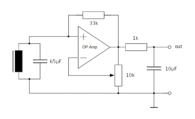
Here is my first circuit:
|
Regenerative Receiver
The OP Amp (¼ LM324) is wired as a negative impedance converter followed by a passive low-pass filter. The
latter has a cut-off frequency of approx. 16 Hz and is necessary to block the omnipresent 50 Hz signal radiated by
the general power grid in Europe. The degree of regeneration is adjusted with the 10k potentiometer. It has to be
set to the point where the circuit is almost on the verge of oscillation. This is where the receiver is most
sensitive and selective. Since 7.8 Hz is in the (non-audible) infrasound region, an oscilloscope is the detector
of choice.
The resonance frequency of the circuit near the point of oscillation can be checked by connecting the non-inverting (+)
input of the OP Amp to a function generator through a 1 MΩ resistor.
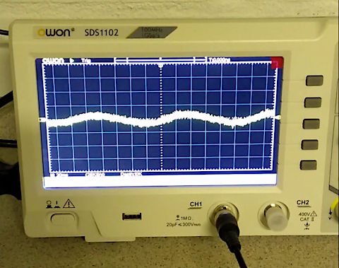
The picture shows how the received 7.8 Hz signal looks:
|
Oscilloscope Image of 7.8 Hz Signal
The signal is rather weak and noisy. Part of the noise is generated by the digital oscilloscope itself and becomes visible
when the latter is set at the highest sensitivity level. I further found that the circuit is rather sensitive to interference
from near-by electrical appliances in the household, e. g., switches, relays, thermostats, fluorescent lamps, etc. Any
incoming electromagnetic pulse triggers a damped oscillation of the resonant circuit. To increase the distance from any
sources of interference, I moved the heavy transformer from the basement to the attic and connected it to the receiver
circuit through a coax cable.
As with ferrite antennas, the axes of the transformer coils should be aligned with the direction of the magnetic field lines,
i. e., perpendicular to the assumed great-circle direction of the wave origin (most thunderstorms occur in southeast Asia
or eastern Africa). The transformer should lie flat on the ground because a cloud-to-earth lightning radiates electromagnetic
waves with vertical polarization, i. e., the magnetic field lines run horizontally.
One question remains unanswered: Is the signal thus detected really the Schumann Resonance or is it just part of the general
noise level in this frequency range? This is hard to tell. When setting the resonant circuit at various frequencies in the
vicinity of 7.8 Hz, the oscilloscope still shows a similar picture, i. e., a lot of low-frequency noise is definitely present.
Since regenerative receivers do not have a well-defined amplification factor, is is extremely difficult to compare signal
levels at different frequencies. A spectrum analyzer is probably required for a definite answer.
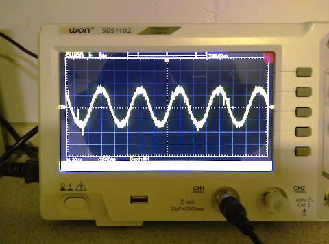
However, an interesting side effect was the observation of a rather strong signal at 16.7 Hz for which I had no explanation
until I remembered that some European countries, among them Germany, maintain a separate AC power grid with this frequency for
their railroad systems. Although the nearest railroad tracks and associated overhead lines are 2 km (≈ 1.2 miles) away
from my house, their stray magnetic field is clearly detectable here. This gives an impression of the sensitivity of this
simple receiver circuit. The following picture shows the 16.7 Hz signal:
|
Oscilloscope Image of 16.7 Hz Signal
Presently, I am planning to design an improved receiver with a low-noise operational amplifier, a tunable input circuit, an additional amplifier stage, and a variable active bandpass filter.
Stay tuned...