High Voltage and X-Ray Experiments
Text and Graphics Copyright © 2005 − 2008 Henning Umland
The following descriptions are given for the purpose of information only. I do not encourage ANYBODY to conduct experiments like those shown below, and I do not assume liability for any damage resulting from such experiments. People working with high voltage and X-rays should have a solid background in physics and electronics and should know what they are doing. The high voltage sources described here are much more powerful than generators of static electricity like, e. g., influence machines, Van de Graaff generators, etc. High voltage can kill instantly, X-rays in the long run (radiation sickness, cancer) if not handled properly.
Building a 120 kV Power Supply
Half-wave multipliers have the disadvantage of rather bad voltage regulation (voltage drop) and ripple (pulsating voltage) under load. In order to have a versatile HV power supply with improved performance, I decided to build a full-wave multiplier driven by two potential transformers in push-pull mode. The multiplier has three doubler stages and is designed for a maximum output of 120 kV DC:
|
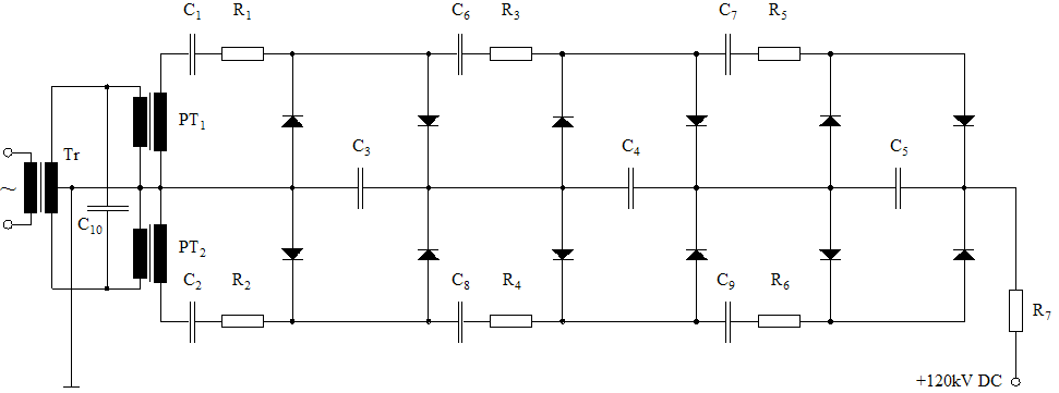
120 kV Full-Wave Multiplier Circuit
C1...C2 = 50 nF / 20 kV, C3...C5 = 44 nF / 40 kV, C6...C9 = 22 nF / 40 kV, C10 = 40 μF / 400 V~, R1... R2 = 5.6 k / 10 W, R3...R6 = 10 k / 10 W, R7 = 50 k (5 × 10 k / 25 W)
The circuit certainly differs from commercial designs, but the home experimenter has to make the best of those components he has available while the industrial designer is in the lucky position to develop the optimum circuit from scratch (unless inhibited by marketing people, accountants, etc.).
Tr has a secondary voltage of 2 × 115 V, but the transformer easily tolerates 20 % overvoltage in intermittent service. In contrast to the first multiplier, the negative lead is grounded. This makes it easier to use a Coolidge tube (a high-vacuum X-ray tube with a heated cathode). Otherwise, a heating transformer with a very thick insulation between primary and secondary coil would be required. Tr is driven by a 280 V / 2 kW variable transformer (not shown). Therefore, the output voltage can be adjusted continually.
The photo shows the mechanical set-up of the circuit. This time, I chose a more permanent design. I was tempted to put everything except the transformers under oil, but I decided to stay with an open arrangement because this makes it much easier to modify the circuit if necessary. Since the multiplier is not meant to run in continuous service, the corona discharges and the ozone stench shouldn't be such a bad problem (not as bad as messing around with oil). After all, the whole thing is experimental. To avoid arcing to ground, the circuit is set up in the form of two vertical columns. The capacitors and diodes are attached to two polypropylene tubes with cable binders (quick and cheap). Actually, this is a combination of two interconnected half-wave multipliers. The damping resistors (R7) are located in the horizontal tube at the top. The monster is 1.2 m (4 ft.) tall.
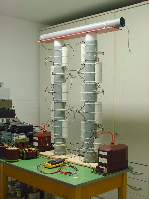 |
Mechanical Design of 120 kV Multiplier
During the first test run, I drive the multiplier to almost 130 kV for about a minute. There is a loud hissing noise. In the dark, I observe strong corona discharges, particularly at the third doubler stage where the highest voltage occurs. There are blue flames emanating from the sharp edges of the metal clamps I used to wire the diodes. The electrical field surrounding the machine is literally hair-raising. Fluorescent lamps in the room start flickering. It works!
Multipliers can exhibit a considerable voltage drop under load which should not be ignored. The following diagram
illustrates the voltage-load characteristics of the above circuit:
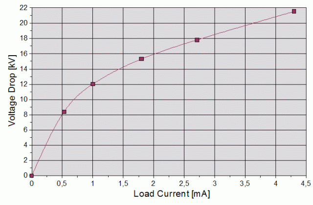 |
An initial load current of 0.5 mA reduces the output voltage by 8 kV. At higher loads, the curve flattens out, and the differential voltage drop approaches 2.5 kV/mA.
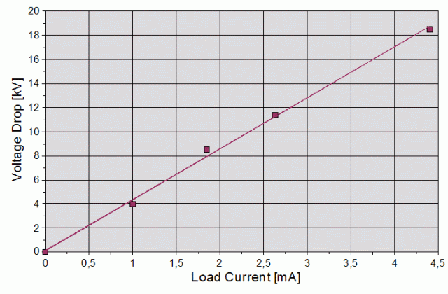
Out of curiosity, I replace Tr, which is rated 550 W, with a similar 2 × 125 V / 3 kW transformer. Now, there is a virtually linear relationship between voltage drop and load current (see below). This is the usual behavior of voltage multipliers under moderate load. I suspect that the stray inductance of Tr has an influence on the voltage-load characteristics. The big transformer has coaxial coils whereas the small one has primary and secondary coils arranged side by side. I decide to stay with the big transformer because the output voltage at a given current is easier to predict (voltage drop = 4.25 kV/mA, output impedance = 4.25 MΩ). At a load current of 4 mA, for example, the total voltage drop is 17 kV. Thus, an output voltage of 100 kV at 4 mA (400 W output power) is available when setting the open-circuit voltage at 117 kV. Accordingly, a no-load voltage of 122.5 kV would still produce an output voltage of 80 kV at 10 mA (800 W). This should be sufficient for most X-ray experiments. Measuring voltages in the 100 kV range is not quite easy. I used arrays of 6 MΩ / 5 W resistors in series with a current meter for these measurements. Although I was rather cautious, several of the resistors blew up in a cloud of smoke. Others degraded less spectacularly but became useless due to changed characteristics. The no-load voltage can be calculated from the peak voltage measured at the primary coil of PT1 or PT2.
 |
HV accident:
The following is a description of a minor accident I had. I am not particularly proud of it. Nevertheless, I am going to give a detailed account here in order to remind people to be caucious when working with high voltage. Stay clear of the equipment and think twice before touching anything!*
After completing the first test run of the multiplier, I wanted to discharge the capacitors with a series stack of 5 heavy-duty 10 kΩ wire resistors. The resistor stack shown in the diagram (R7) and photo hadn't been installed yet. I had put the resistors in a thick PVC tube which I held in my left hand. My right hand held a ground cable attached to one end of the resistor stack. When I approached the hot terminal of C5 with a short piece of wire connected to the other end of the resistor array and protruding from the mouth of the plastic tube, sparking occured, as expected. Unfortunately, I forgot that the discharge path of a spark has almost no resistance. Thus, the full capacitor voltage dropped across the resistor array for a tiny fraction of a second. This was sufficient to puncture the tube wall. As a result, the greatest part of the discharge current took a shortcut through my arms and chest instead of flowing through the resistors. The shock knocked me down immediately. I was not totally unconscious, but I remember everything around me getting dark, as if somebody was dimming the lights down within one or two seconds. When the blackout was over after a few seconds, I found myself lying on the floor. My fingers were numb, and I felt rather shaky for several minutes. After I recovered, I noticed a charred hole in my finger (see photo). Later, I found a similar hole in the PVC tube. As time passed, the burn hole in my finger turned into something like a permanent black tattoo (caused by carbon particles embedded in the scar tissue). This should be proof enough that high voltage should be taken seriously.
*A few know-alls and high priests of occupational safety have criticized me harshly for my experiments. Some disgruntled old man from Baraboo, Wisconsin, even went so far as to call me an idiot, a moron, and a Darwin Award nominee (anything else?). Apart from being amused, I believe these people either didn't read my text thoroughly enough and missed some important points or, worse, lack the mental capacity to understand what they read. Lack of mental capacity (dementia senilis? ) may also be the reason why some people resort to mud-slinging instead of seeking an objective discussion. To make it clear, I do NOT promote irresponsible behavior. By the way, nobody is obliged to look at these pages, and people who don't like them are free to leave them. Discede, cacator. Non est hic tutum culum aperire tibi...
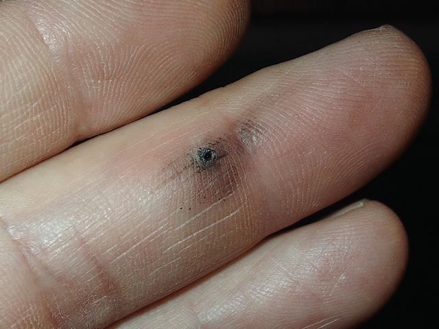 |
Burn Hole
Upgrading the multiplier:
In order to decrease the output impedance of the multiplier further, I install a few additional capacitors. C1 and C2 are doubled to 100 nF each. In the same manner, C6 through C9 are increased to 44 nF each. Further, a 20 nF capacitor (C12) is installed between ground and the hot end of C4. The latter step looks somewhat unconventional, but I happened to have this capacitor in stock and was looking for a useful application. C12 brings an additional reduction of voltage drop and ripple. R7 is doubled to 100 kΩ in order to limit the pulse current in case of accidental arcing. If a very "stiff" output is required, the voltage can be picked up at the hot end of C12. In this way, the circuit works as a quadrupler, and a maximum DC voltage of 80 kV is available. The modified circuit is shown below.
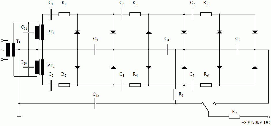 |
80/120 kV Full-Wave Multiplier Circuit
C1...C2 = 100 nF / 20 kV, C3...C9 = 44 nF / 40 kV, C10...C11 = 5 μF / 400 V~, C12 = 20 nF / 87 kV,
R1...R2 = 2 k / 10 W, R3...R4 = 5.6 k / 10 W, R5...R6 = 10 k / 10 W, R7 = 100 k (18 × 5.6 k / 10 W), R8 = 10 k / 10 W
The modifications reduce the output impedance of the circuit from 4.25 MΩ to about 2.5 MΩ. Thus, the circuit produces a voltage of 100 kV at 10 mA load current (P = 1 kW) when the no-load voltage is set at 125 kV. Here is a photo of the set-up with the additional capacitors installed:
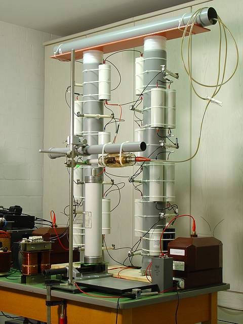 |
Improved 120 kV Multiplier (with X-Ray Tube)
Will be continued...