High Voltage and X-Ray Experiments
Text and Graphics Copyright © 2005 − 2008 Henning Umland
The following descriptions are given for the purpose of information only. I do not encourage ANYBODY to conduct experiments like those shown below, and I do not assume liability for any damage resulting from such experiments. People working with high voltage and X-rays should have a solid background in physics and electronics and should know what they are doing. The high voltage sources described here are much more powerful than generators of static electricity like, e. g., influence machines, Van de Graaff generators, etc. High voltage can kill instantly, X-rays in the long run (radiation sickness, cancer) if not handled properly.
Building a Simple X-Ray Machine
Here are Some Facts about X-rays.
Safety issues:
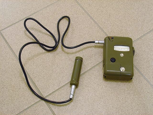
Experiments with X-rays should never be conducted without monitoring the radiation with a GM counter, ionization chamber, or similar instrument. Otherwise, one never knows exactly at which voltage a tube starts radiating, where the direction of maximum radiation intensity is, and if the chosen shielding gives enough protection. The counter shown below is almost 30 years old but still works very well. The model was used in civil defence.
|
X500 GM Counter (Manufacturer: Graetz, Germany)
Here is another counter of high quality. This one was used in the German military in the 1980s.
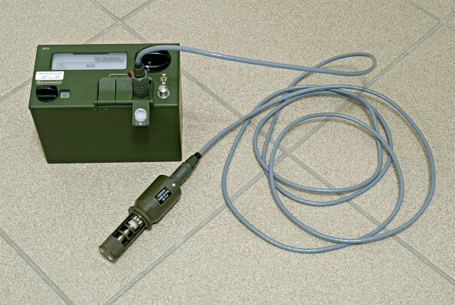 |
SV500 GM Counter (Manufacturer: FAG Kugelfischer, Germany)
Some counters are rather insensitive to soft X-rays (U < 30 kV). Therefore, a counter indicating nothing does not prove that there is no radiation present. With the counters shown above, I was able to detect radiation at an anode voltage of 10 kV (accurate measurement is not possible in this range). Even X-rays of low energy penetrate soft tissue and cause cell damage. To be safe, one should ALWAYS stay away from a vacuum tube powered with more than a few kilovolts.
Before starting any experiment, one has to consider how to shield oneself and other people from the radiation emitted by the X-ray tube. Unlike hospitals and research institutes, the home experimenter is usually not in the lucky position to own a hermetically shielded X-ray room. When working with relatively soft X-rays (U < 70 kV), a 20 cm (8 ") layer of concrete, sandstone, or brick is usually sufficient to reduce the radiation to a tolerable level, at least for short-term exposure. I found that behind a 20 cm sandstone wall, the radiation emitted by a tube running at 70 kV and 1 mA was reduced to about twice the normal background radiation (the distance between tube and wall was 2 m). Construction materials of low density like wood, plastic, etc. do not nearly provide sufficient radiation protection, and people living in light-construction houses should better refrain from experimenting with ionizing radiation. Apart from seeking shelter behind a wall, one should stay as far away from the tube as possible because the radiation intensity decreases with the square of the distance. This requires the tube to be operated by remote-control. The position of the operator should be on the anode side of the tube, preferably near the extended tube axis, because the anode material (usually tungsten and copper) works as an efficient shield*. However, a smaller portion of radiation caused by secondary electrons and backscatter inside the tube is emitted in all directions and must not be ignored. In addition to the above safety measures, I made it a habit to wear a lead apron (0.35 mm Pb) protecting the torso and upper thighs.
*Caution: These considerations refer to tubes emitting sideways. There are tubes with a different design emitting radiation along the tube axis.
Radiation protection becomes more difficult as the tube voltage increases because harder X-rays are more penetrative. I found that beyond 100 kV, one has to put at least two stone walls (20 cm each) between oneself and the tube to reduce radiation to a tolerable level. To make things more complicated, harder X-rays produce a significant portion of back-scattered radiation when hitting matter (even air!). Radiation produced by backscatter appears to come around the corner and can be emitted by walls located behind the operator. This has to be checked by turning the Geiger counter in all directions. It can be quite difficult to find a position where one is relatively safe from both, direct AND back-scattered radiation, depending on the design of the building. It goes without saying that the experimenter is also responsible for the safety of other persons living in or near the house.
The radiation dose a person can absorb without experiencing negative long-term health effects is a matter of debate. Among other factors, individual disposition seems to play a role. In any case, the radiation dose received during experiments should be kept as small as possible (not much above the normal background radiation). People afraid of even small radiation doses better keep away from X-ray experiments. They should also think twice, however, before boarding a long-distance flight since the radiation level at 33000 ft altitude (cosmic radiation, solar wind) is not negligible. Everyone who ever took a Geiger counter on a flight knows this.
X-ray tubes:
Here comes a nice collector's item, a historic cold-cathode tube. This is how X-ray tubes looked at the beginning of the 20th century, before they where superseded by the more efficient hot-cathode tubes invented by William Coolidge. The tube is not marked, but it looks like manufactured by Pressler, Germany. The cathode is on the left side, the tilted target (anode) at the center of the glass bulb. The anode terminal is on the right side. The tube must be a late model because it is a two-electrode design (earlier models had three electrodes). Cold-cathode tubes contain a small quantity of gas (0.01 ... 0.1 mbar) which becomes ionized when high voltage is applied. Bombarded with positive ions, the cathode releases electrons which are accelerated toward the target (anode) where they cause emission of high-energy photons (X-rays) upon impact. The cathode surface has a spherical curvature to focus the electrons on a small spot on the target surface. This improves image definition.
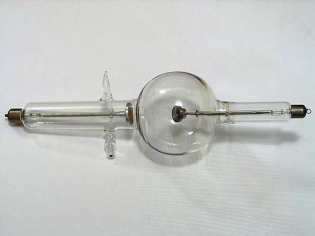 |
Cold-Cathode X-ray Tube
The tube shows a strange, almost unpredictable behavior. I apply a plate voltage of 40 kV DC, and nothing happens. No current, no emission! At about 70 kV, there is suddenly a bright green flash and a crackling noise. I immediately reduce the voltage to avoid damaging the tube. After ignition, the tube keeps fluorescing (and emitting X-rays!) even at a voltage of less than 20kV. I turn the power off and wait for a few minutes. Then I apply 30 kV. Nothing happens until after some time spontaneous ignition accompanied by a green flash occurs again. The tube emits a flickering green light. Accordingly, the current is subject to rapid fluctuations which make it almost impossible to read the current meter. The estimated average current at 30 kV is about 500 μA. The tube is obviously not designed for high power dissipation because the anode head is rather small. Heat is almost exclusively dissipated by radiation. The tube is probably best operated in the old-fashioned way, i. e., with an induction coil giving off short pulses of very high voltage (≥ 100 kV). The tube might also work with a Marx generator. Cold-cathode tubes exhibit not only short-term instability but gradually lose gas by absorption to surfaces (ion implantation). This decreases the average current at a given voltage. The above tube has a small reservoir with a piece of coal in it. Heating this device, called regulator, releases a small quantity of gas absorbed by the coal and restores the proper gas pressure.
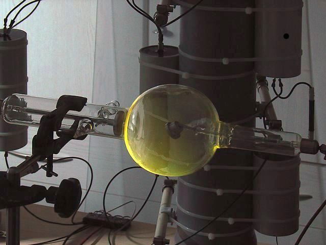 |
Fluorescing Tube
Some time ago, I purchased a used X-ray tube of unknown origin, possibly from a dental X-ray machine (see photo). This is a hot-cathode, high vacuum tube. The design was developed by William Coolidge in 1913 and is still in use today. The glass bulb of this specimen has a acquired a slightly brownish tint caused by traces of condensed metal and the effects of radiation. This is more or less a cosmetic issue. Otherwise, the tube seems to be in good condition. The filament is ok, and the tungsten inlay (target) in the copper anode shows very little wear. The latter is a result of the electron bombardment causing the target metal to evaporate slowly. Apart from a serial number, the tube is not marked, so I have to find the best operating parameters empirically.
 |
Coolidge Type X-Ray Tube
As a first check, I apply a variable plate voltage to the unheated tube. There is no measurable plate current at 40 kV, at 60 kV the tube draws 2 μA. At 80 kV, the plate current rises to 20 μA. Now, the glass bulb shows a slight fluorescence in the dark, and stray radiation becomes significant. This seems to be about the maximum voltage the tube can handle. The low current flowing through the unheated tube is a result of residual gas which becomes ionized in the strong electrical field.
In contrast to a cold-cathode X-ray tube, a Coolidge tube has the advantage that the plate current is less dependent on the plate voltage over a wide range because the cathode (heated tungsten filament) works in saturation mode. The plate current is predominantly controlled by the filament current (controlling the cathode temperature). Therefore, radiation intensity (photon flow) and "hardness" (photon energy) can be adjusted more or less independently. To find the best filament voltage for my experiments, I connect the filament to a variable transformer and increase the voltage slowly. At 4.0 V (filament almost white hot), the tube draws a plate current of approx. 1 mA (Ua = 40 kV). This seems to be a reasonable value for first experiments. Of course, a hotter filament would emit more electrons, but a moderate temperature will increase the lifetime of the tube considerably. There is no need for a particularly high radiation intensity because I can simply increase the exposure time of the film if necessary.
Radiation becomes detectable at an anode voltage of about 10 kV. Below this voltage, most of the X-ray photons are
too "soft" to penetrate the glass bulb. Moreover, the plate current drops off at lower voltages. I decide to use 50 kV plate voltage for the time being. At 50 kV and 1 mA, the plate dissipation is 50 W. Without extra cooling, the tube should be able to run for a minute under these conditions without overheating. This would result in a total energy dissipation of 3000 J per shot. Keeping the tube clean and dry is important, otherwise, arcing across the glass envelope may occur.
Below is a photo of a bigger Coolidge tube manufactured by COMET, Switzerland (in comparison with the smaller one described above). The tube is as good as new (NOS) and in excellent condition. The brown discoloration of the glass envelope is a result of the burning-in process. New tubes have to run a number of hours to remove residual gas. The surface of the tungsten target does not show any sign of pitting.
 |
2 Coolidge Tubes
Again, I have no technical specifications and have to find the best operating parameters empirically. According to the size, the tube should be good for 100 kV. The picture below shows the tube ready for the first test run. Since the tube is rather heavy, I do not dare to hold it with a clamp because the stress acting upon the glass envelope might be too much. Instead, I use cable binders to suspend the tube under a polypropylene pipe*.
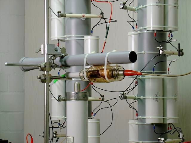 |
COMET Tube Ready for Test Run
* I found that polypropylene sewage pipes, cable binders, and fiber-reinforced adhesive tape are versatile construction elements for setting up experimental high voltage circuits.
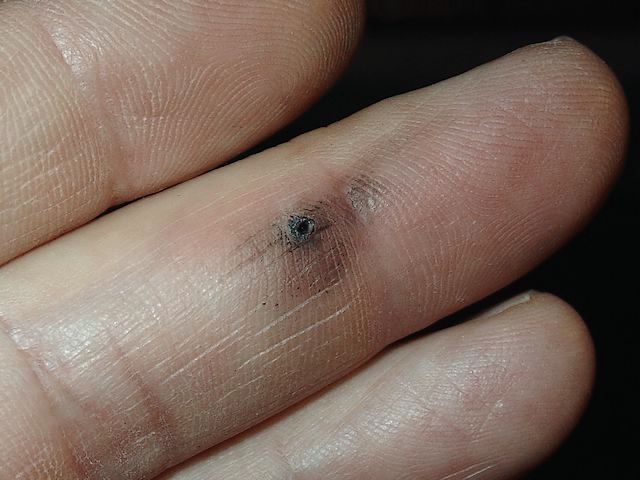
In the 100 kV range, the possibility of arcing becomes a major issue which has to be considered when designing an
experimental setup. I observed spark lengths of 15 cm (6") between electrodes with moderately sharp edges. Arcing is not only a safety risk (see picture) but may also result in the destruction of valuable components. As a precautionary measure, I install a plastic tube to shield the filament leads. To check the vacuum, I connect the unheated tube with the multiplier and increase the anode voltage cautiously. The vacuum is excellent. Even at 110 kV, the tube draws less than 3 μA. There is a hissing noise, and I observe corona discharges around the anode terminal. Next, I reduce the anode voltage to 40 kV and increase the filament voltage until the tube draws 1mA anode current. This happens at 3.25 V. Now, I raise the anode voltage to 110 kV again. The corona discharges are much stronger and louder than without heating, probably because the radiation ionizes the air surrounding the tube and makes it more conductive. Still, arcing across the tube does not occur. I try to suppress the corona discharges by sliding a short piece of plastic tube over the anode terminal and hv clamp. Surprisingly, there are loud, popping noises now (sounding almost like Chinese firecrackers). I suppose there is a sudden discharge into the air everytime enough ions have accumulated inside the plastic tube. Consequently, I remove the
plastic tube again. The anode dissipates 110 W under the above conditions. Since there is no cooling, the tube must not run continuously. This is not a problem because I intend to use an intensifying screen for future experiments, reducing the exposure time from minutes to seconds.
During the second test run, I turn the GM counter on. The radiation is so penetrative now that the protection provided by a 20 cm stone wall is not sufficient anymore. Moreover, I measure strong radiation "around the corner" which is caused by backscatter. After some searching, I find a new position for myself which is reasonably safe from direct and back-scattered radiation.
>
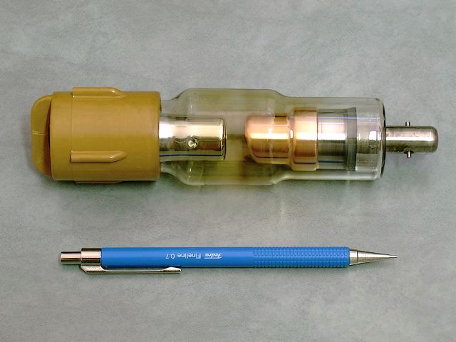
Here comes a tube with a hollow anode head. It has about the length of a pencil and was probably made for dental X-ray equipment. The design differs from the other tubes insomuch as the tungsten target is inside a cavity of the copper anode. The electron beam enters the anode cavity through a hole facing the cathode. The radiation exits the anode head sideways through a second hole. This design reduces stray radiation caused by secondary electrons. The tube is rated 70 kV. My own measurements confirmed that the tube produces very little stray radiation and that almost all radiation exits through the hole in the anode. The tube is fully functional. The tungsten target has a polished surface and does not show any signs of wear.
 |
Hollow-Anode X-Ray Tube (Manufacturer: Chirana, former Czechoslovakia)
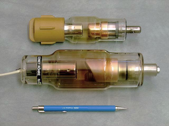
The next photo shows a bigger tube manufactured by COMET (in comparison with a smaller dental X-ray tube). It has about the size of a wine bottle. Here, the radiation exits the side of the anode head through a round beryllium window (beryllium has a very low absorption coefficient). The tube should be good for at least 150 kV, probably more.
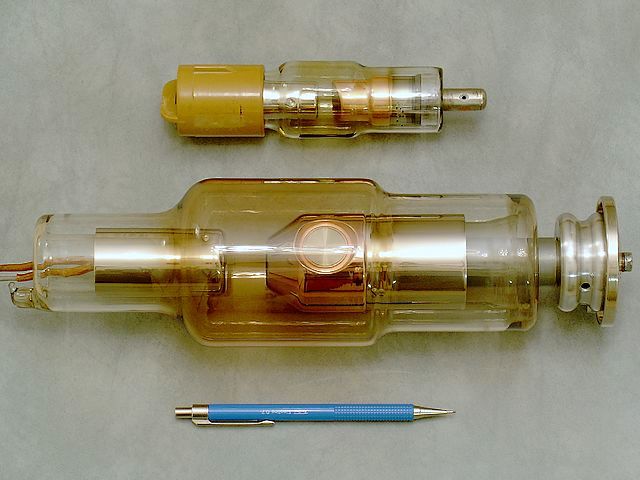 |
X-Ray Tube with Beryllium Window
After completing the 160 kV multiplier, I make a few test runs. The tube tolerates the full voltage without arcing across the glass envelope. The vacuum seems to be ok since the cold tube draws no measurable current and emits only weak bursts of radiation. Next, I slowly increase the filament voltage. At 4.0 V, the tube draws about 2.5 mA anode current (150 kV anode voltage, 375 W power dissipation). During the experiment, I take shelter behind an armored gun cabinet and two stone walls. Measured in the direction of the tube, the radiation level appears tolerable. However, the GM counter indicates stronger radiation when I point the probe away from the tube. The radiation coming through the door and hitting the wall behind my back induces secondary radiation (backscatter, X-ray fluorescence). I finally decide to operate the equipment from outside the house. This tube seems to produce a comparatively low output. I suspect the tungsten target is eroded or cracked due to abuse by the former owner. Unfortunately, I cannot inspect the target because it is hidden inside the anode cavity. There is, however, a thin layer of grey metal, probably tungsten, deposited around the mouth of the anode cavity which may be an indication for heavy overload (evaporated filament material). For my kinds of experiments, the problem is more or less marginal since I can simply increase the exposure time.
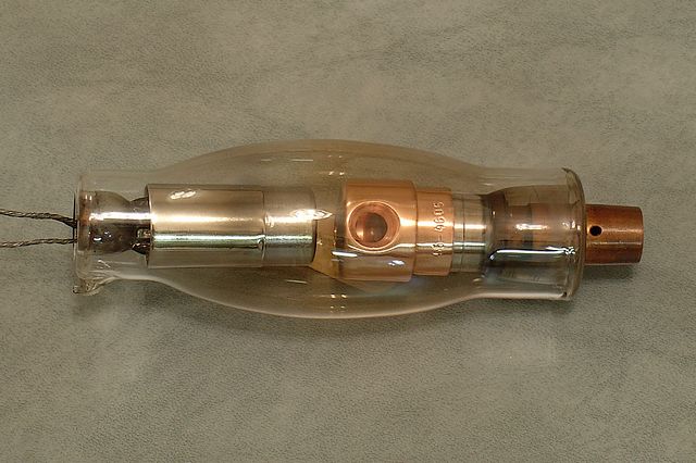
The next photo shows my latest purchase, a hollow-anode therapy tube rated 200kV / 20 mA. The total length of the tube (without filament leads) is 32 cm. The anode stem is hollow and can be cooled with oil. The tube is probably about 50 years old but in mint condition (NOS).
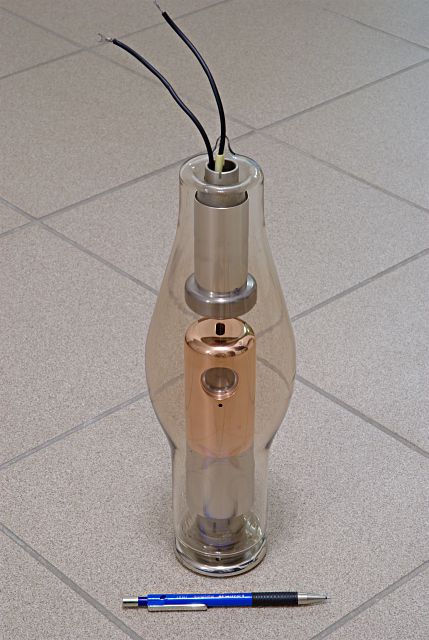 |
200 kV Therapy Tube (Manufacturer: Rörix, former German Democratic Republic)
A simple X-ray machine:
The photo below shows the set-up of my experimental X-ray equipment. The heating transformer is in the left foreground. Below the tube is a 4×5" sheet film holder from a studio camera. The vertical distance of the tube axis from the film is 40 cm (the photo shows 30 cm).
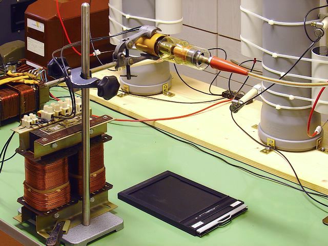 |
Experimental X-Ray Machine
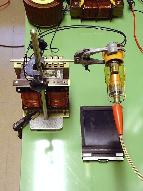 |
X-Ray Machine from Above
Here is the circuit diagram. The current meter is in the cathode lead to avoid insulation problems. The iron cores of the transformers have to be grounded. Otherwise, they might charge up until sparking-over to the coils occurs. This is due to ionized air caused by the many corona discharges.
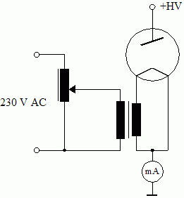 |
Circuit Diagram of X-Ray Machine
The major problem I observed with small X-ray tubes is power dissipation. Even at only 50 W dissipation (50 kV @ 1 mA), the anode gets hot within about 2 minutes. This is particularly annoying at low voltages (30 ... 40 kV) where a very long exposure time is necessary due to reduced tube efficiency. Since the evacuated glas bulb of the tube almost acts like a thermos bottle, it is difficult to get rid of the heat, and the anode needs a very long time to cool down. Therefore, multiple exposures are no practical solution to the problem unless one is patient enough to wait for hours. The only way of cooling the tube more efficiently is by thermal conduction along the anode terminal. I decide to use my metal lathe and make a round heat sink with cooling fins and a sleeve fitting tightly on the anode terminal. Here is the result:
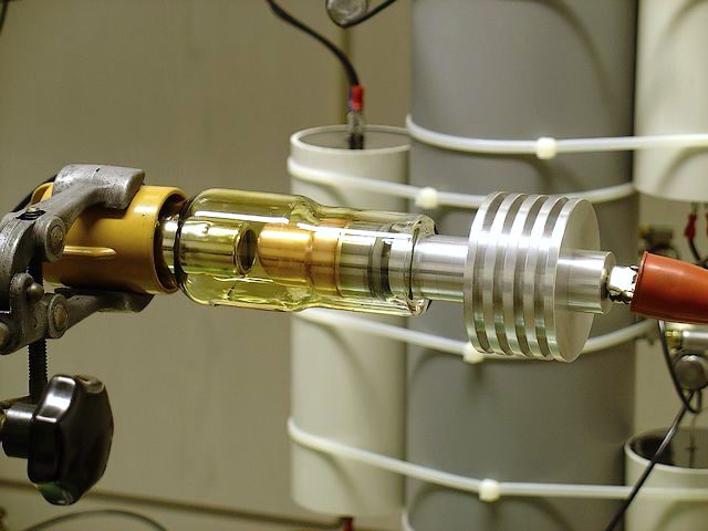 |
Small Tube with Aluminum Heat Sink
With the heat sink attached, the tube can easily dissipate about 10 kJ per shot. With forced-air cooling (blower), continuous service should be possible. At voltages higher than 70 kV, occasional arcing between the rim of the heat sink and the metal clamp holding the tube occurs (looks spectacular).
I am not quite satisfied with the photographic exposure control yet since I have no stabilized filament voltage (the anode current changes rapidly with changing filament voltage). Moreover, the filament needs a few seconds to warm up and to cool down, respectively. The anode voltage, too, needs some time to build up when turned on and to drop when turned off. I also observe that the anode current is not quite independent of the anode voltage. The tube draws 1.3 mA at 110 kV when adjusted so as to draw 1 mA at 40 kV. At a given anode voltage, the photographic density is a function of the electric charge flowing through the tube. To measure this charge, I install a capacitor in the cathode lead which works as an integrator (see below).
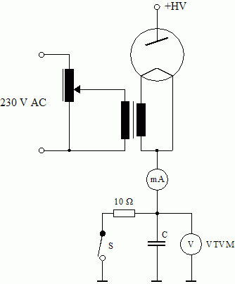 |
Improved Circuit with Integrator
If, for example, the capacitance of C were 1000 μF, a charge of 1 mAs would result in a voltage of 1 V, independent of any current fluctuations (the capacitor voltage varies in proportion with the charge). I use two paper/oil capacitors with a total capacity of approx. 1500 μF. Thus, a capacitor voltage of 1 V is equivalent to a charge of 1.5 mAs. The time constant resulting from C and the internal resistance of the vacuum tube volt meter, VTVM (Ri = 11 MΩ), is 16500 seconds. Therefore, the capacitor voltage remains virtually constant for some time after the anode current stops flowing. Electrolytic capacitors are not suitable for such a circuit because of their relatively high and unpredictable leak current.
Before starting the experiment, the switch, S, is closed to discharge C. This being done, the switch is opened. Next, I turn the multiplier on and wait a few seconds until the hv has become stable. Then, I turn the filament voltage on and watch the VTVM. About 1 volt below the desired voltage, I turn the filament off (the anode current does not stop instantaneously because of the heat stored in the filament). At last, I turn the multiplier off and discharge the hv capacitors (safety measure). Filament voltage and hv are turned on and off by relays which are operated from my radiation-safe "control room". The latter also houses the current meter and the VTVM which are connected with the circuit by long cables.
Will be continued...